Thursday, 3 March 2011

Climbing Buttress


The lifts and stairs that fit in this flying buttress extension.

These extensions are not solid. The solid parts only represent the space that can be filled with structure here.


Wednesday, 2 March 2011

Vertical Grid System


Every flying buttress extension is seen as a perpendicular ground level, and starting from south eastern side, the grid gets bigger by 0.5m at every flying buttress extension. Red is on the both sides of the second flying buttress - meaning: none of the spaces are distorted to meet the adjacent grid, they are simply straight extrusions of the frame.


Tuesday, 1 March 2011

Studying the Buffer Zone


Space in-between can be seen as a 3D masterplan base for my micro city  - the flying buttress becomes the plots / city blocks. These are only the potential locations - grid for the space in between. Only a few of them might be used for occupation out of hundreds you see here.

Saturday, 26 February 2011

Flying Buttress Development


After having very helpful tutorials with Matt and Paul Lau (Technical Studies) on friday. I am working on a deeper analysis by also recording the process. So far, the project has been a design from large/overall design towards smaller scale details, now I will try a reverse approach by starting very small systems developing into a larger system.


Thursday, 24 February 2011

Wednesday, 23 February 2011

Horizontal Connections


This is the first test for connecting the extensions with each other.

Columns

This flying buttress type is built by using only 600mm square profile columns. only the extensions for the existing flying buttresses are added to the vertical columns. This version allows an addition of pinnacle like element to the flying buttress extensions.


Also in this version, the distance between the columns are changing in every single extension. For the longest extensions the distance between the columns is 8m while in the narrow extensions the distance between the columns are 1.2m.

Rendering with the afternoon sun.

Moving away from the slab


Instead of a straight extrusion of 2m wide flying buttress all the way until the end of the city block, gradually the buttress extension gets thinner until it becomes 200mm wide in 10 steps.


Carving openings functioning as arches can be a way of moving away from the solid walls.


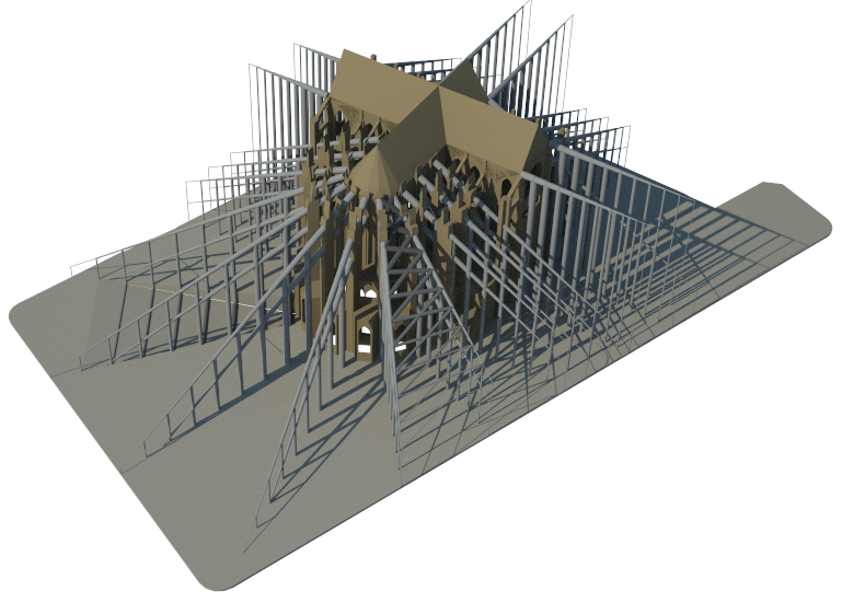
This is the D-O northern extension

8m distance between each of the vertical structure of this extension. Frame gets narrow by 200mm, starting with 2000mm width, ending with 100mm.

Tuesday, 22 February 2011

Flying Buttress Extensions


An updated plan for the cathedral and the Beauvais block around it. Finally everything is under control.

Monday, 21 February 2011

Steel Rings


Flying Buttress extensions will be built with bundled steel rings. However, in this render they merge into each other unrealistically. The larger frame is 20cm in diameter and 6m wide. 

Saturday, 19 February 2011

Refined Structure


The whole block around the cathedral is cleared in this phase.

Extension for the nave is straight since there's no arcs towards the ground like the flying buttresses.


The museum is removed at this point at the eastern end of the cathedral.

New Cathedral Model


i had to start over and create a clean and light cathedral file in the end since its impossible to work with the insane size of the group cathedral model. - no ornament, purely the openings + structure.

Tuesday, 15 February 2011

Flying Buttress Types

step 1

step 2


on site


Scaled Drawings


Finally I have produced the scaled drawings from the point cloud information. This information helps me locating the rose window and temporarily nave closing section.

Thursday, 10 February 2011

Flying Buttress Catalog


These are the simplified structural principles behind the flying buttresses below. Each of them has different potentials to be developed in my version to become a new skeleton around the cathedral.

Defining a Grid

After the jury; the heavy 3d model of the cathedral is replaced by the simple outline and structure of the cathedral. Refined in order to understand its proportions better. This will also enable 3D printing in 1:500 scale


The flying buttress extension - the circular side is limited with the eastern side of the building. Instead of focusing on the space, the focus is the frame - the buttresses now. The heavier lines in this drawing shows only flying buttress extensions, other types of structural extensions are to be added.

Thursday, 3 February 2011

Space Around the Cathedral


A radial system in plan is needed around the cathedral to construct a path that is not random. Therefore I use 48m vectors as the extension of the flying buttresses and existing structure. Only when they extend out of the city block, I shorten them to the new length.  Then I draw only in clockwise direction, perpendicular divisions. The path would be continuous but not a round and perfect walkway.